Game Development Tutorial
I – Choosing Scene and Environment
The first thing we need to do after making a new project is to make a scene. The main scene will be called “EscapeRoom” and the second one will be “Maze”.
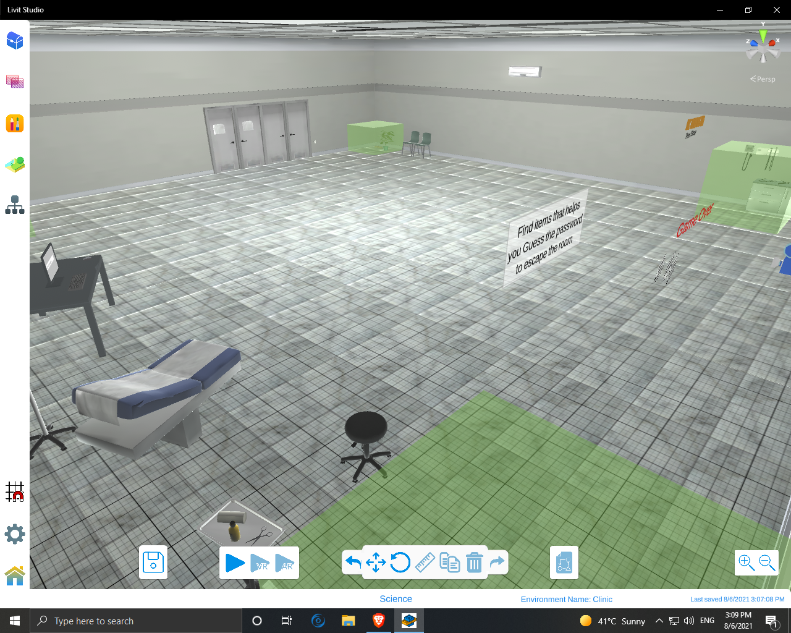
For the main scene, we are going to choose the Clinic environment and the second scene will have the Natural#4 environment.
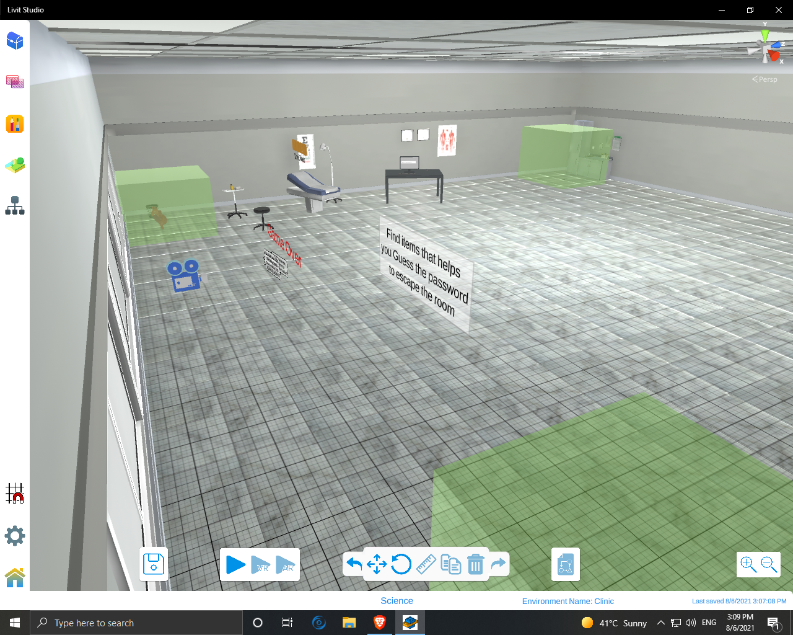
II – Adding Components to the Scene
For the escape room scene, we will add:
- 4 Trigger boxes (One on each corner of the room).
- 4 items in each corner: Heart, Knife, Remote and Map.
- Table and put on it a computer screen, keyboard and a mouse.
- Input field and re-size it to fit in the computer screen in step 3.
- The characters: K 1 0 1 5 H and re-position them to be in the upper center of the player’s camera (when pressing play).
- Add a Coin Sound Effect to any character.
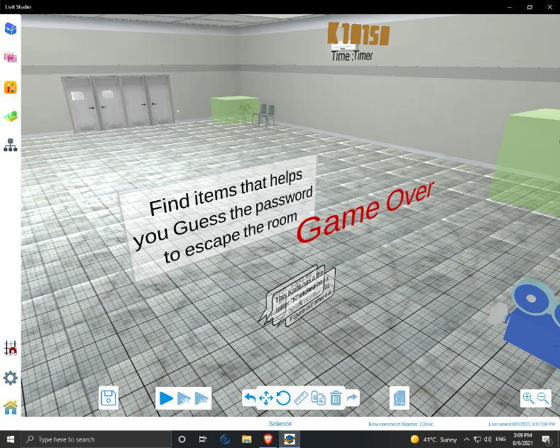
- Two timer Texts: One to Display “Timer :” and the other to be the counter, and re-position them to be under the characters in step 5.
- 4 Text fields to display messages to the player while playing.
- A “Game Over” Text with red color and attach a lose sound effect.
For the Maze scene, we will add:
- Green cubes all over the map to make the maze.
- Trigger Boxes in each intersection.
- Trigger Box and a Treasure Object in the end of the path.
- Attach a winning sound effect to the Treasure Object.
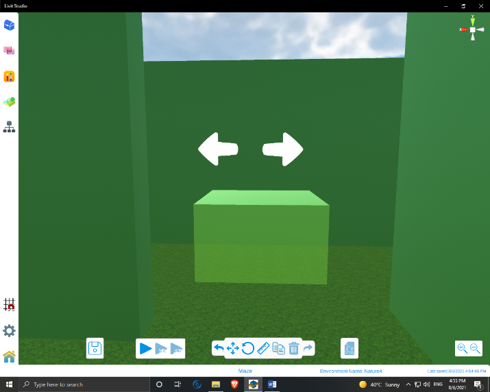
- Right and Left arrows on the wall in each intersection.
- Step 7 and 9 from the previous part.
- A “You Win!” Text with Gold color.
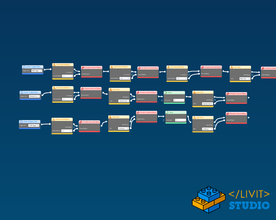
III – Pickups and Trigger Boxes
There are 4 Trigger Boxes, 3 Pick Ups and 1 Popup Question (Fig.1.1 and Fig.1.2). On Entering each Trigger box, the corresponding Pickup character is taken and a UI element of it is shown. This code is controlled in the camera as shown in Fig.2
For the Pickups:
- Put Enter Trigger Box block and select its name.
- Add Get GameObject and select the character object to be shown.
- Add Enable GameObject.
- Step 2 again and add Play Sound.
- Repeat step 2 and 3 for the corresponding Text.
- Add Wait block and write “4” seconds.
- Repeat step 2 for the Text.
- Add Disable GameObject.
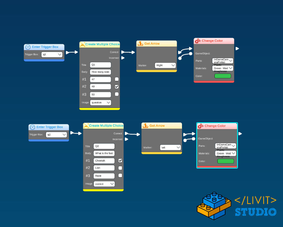
For the Popup Question:
- Put Enter Trigger Box block and select its name.
- Add the Create Multiple Choice block.
- Repeat step 2, 3 and 4 in pickups.
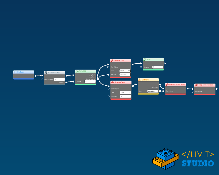
II – UI Elements
The UI elements are all children of the camera. In the beginning, all UI elements are disabled, except the Timer that works with a for loop and a down counter block as in Fig.3 and the game tip text that disappears after 4 seconds Fig. 4. On entering each trigger box a tip appears for 3 seconds to explain the pickup and the character you found that will be enabled upwards. Finally, the “Game Over” text appears after the Timer reaches zero.
For the Timer: (in the camera’s code)
- Put OnStart block.
- Add the For Loop with Down Counter blocks.
- In the loop body Change Text of the timer text to the value of the current loop counter then Wait 1 second.
- In the loop done Change Text of the timer text to Zero the Enable the Game Over Text and Play Sound.
III – Changing Scene
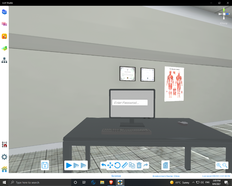
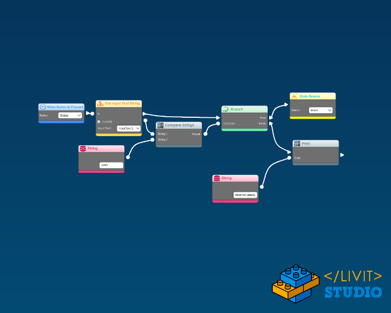
In order to change the scene, you will have to collect all keys to know the password and enter it on the input field in the computer screen (Fig.5). As in the input field’s code in Fig.6. If it is correct you will go to the next level else, an “incorrect password” message will be displayed.
For the Password: (in the input field’s code)
- Put When Button Is Pressed block and add the “Enter” Key.
- Add Get Input Text String then Compare Strings with the String “k45h” (the password).
- Add A Branch.
- If the password is Correct then GoTo Scene “Maze” else print String “Incorrect Password”.
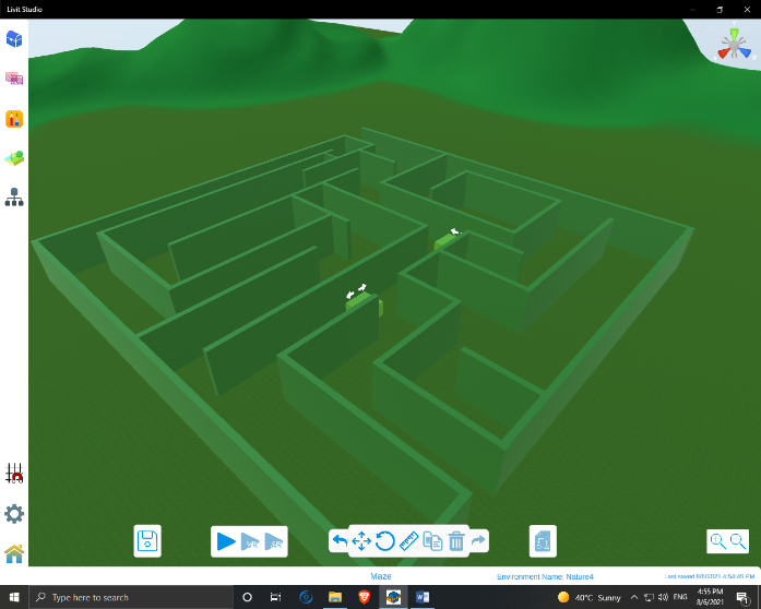
III –Maze Scene
The second scene is a maze (Fig.7) that have similar UI elements (Timer and Game Over) as the previous one, except that in this scene on entering a trigger box a question will appear if your answer is correct, the white arrow will change its color to indicate the right way(Fig.8). This code is attached to the camera (Fig.9).